I have seen engines overhauled due to misfires and hard starts, only for mechanics later to realize it was a failed simple component: the MAF sensor. Before you go down that rabbit hole, let me teach you how to test a MAF sensor and know whether it’s the culprit.
Contents
How MAF Sensor Works
Before determining whether the MAF sensor is faulty, let’s first understand what it is and how it works. MAF is an abbreviation for Mass Air Flow, which is generally the volume of air that flows into your car intake manifold. For the car to burn gas and run, it needs oxygen.
For efficient combustion where there is little to no unburnt fuel, there has to be a balance between fuel and air, commonly known as the air-fuel ratio. This ratio is measured by the car computer, and the MAF sensor is the eye of the computer to see how much air is getting in.
Once the computer knows the volume of air, it determines how much fuel to inject into the engine. If the sensor can’t tell the computer how much air is getting in, the computer won’t know how much fuel to inject, and of course, there will be bad or no combustion.

How the Sensor Measures the Air Volume
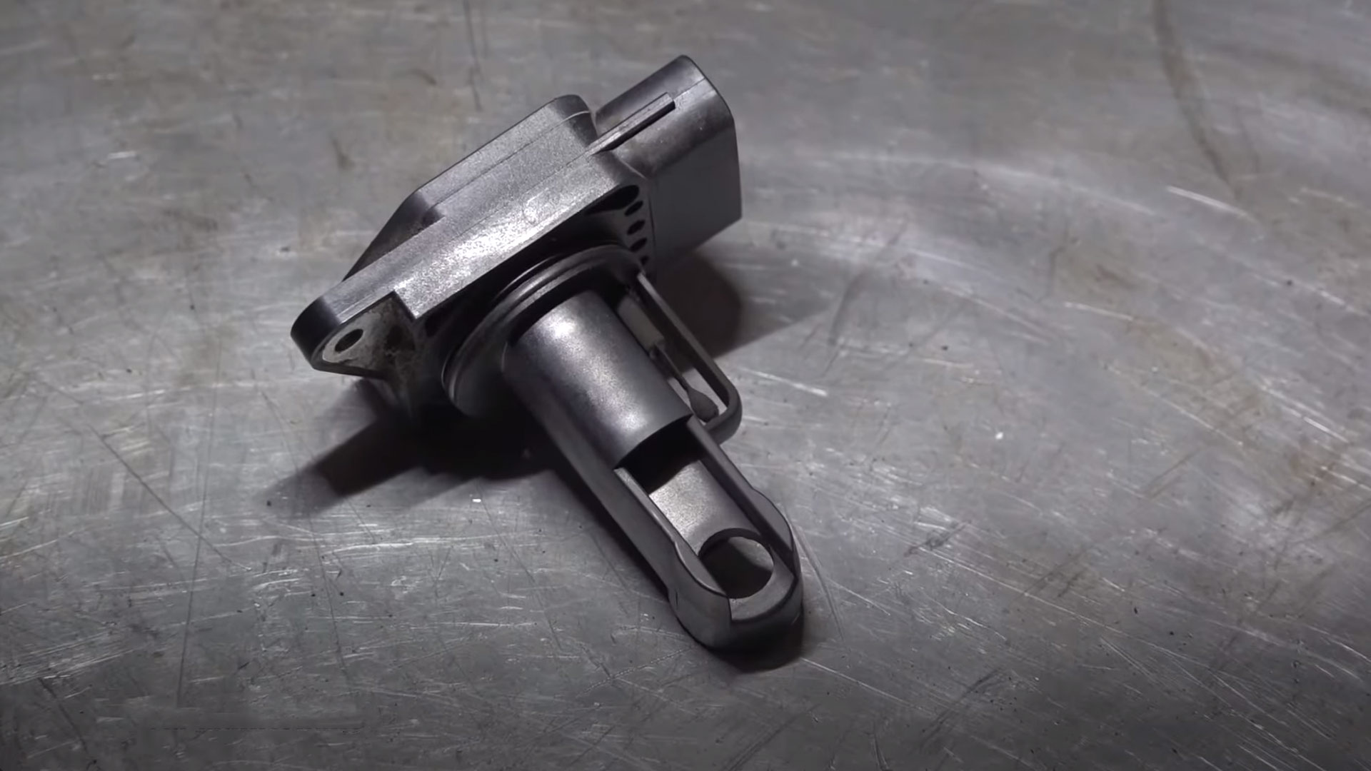
Now, let’s get a little deeper into how this small gadget knows the volume of air passing. Although the design varies across models, most cars use the hot wire concept. Does that sound like robotic science? Well, here is how it works.
The car sends current to a wire inside the sensor, making it hot. Nearby is a temperature sensor that tells the computer how hot the wire is. Normally, when air blows over the wire, it will cool it down. That means the computer needs to send more current to keep the wire hot when more air is blowing.
When the car is idling, only a small current is needed to keep the wire hot. When you press the gas and the butterfly valve opens, more air flows, and more current is needed to keep the wire hot. The chip on the sensor interprets these fluctuations and tells the computer how much air is flowing into the intake manifold.
MAF Sensor Location
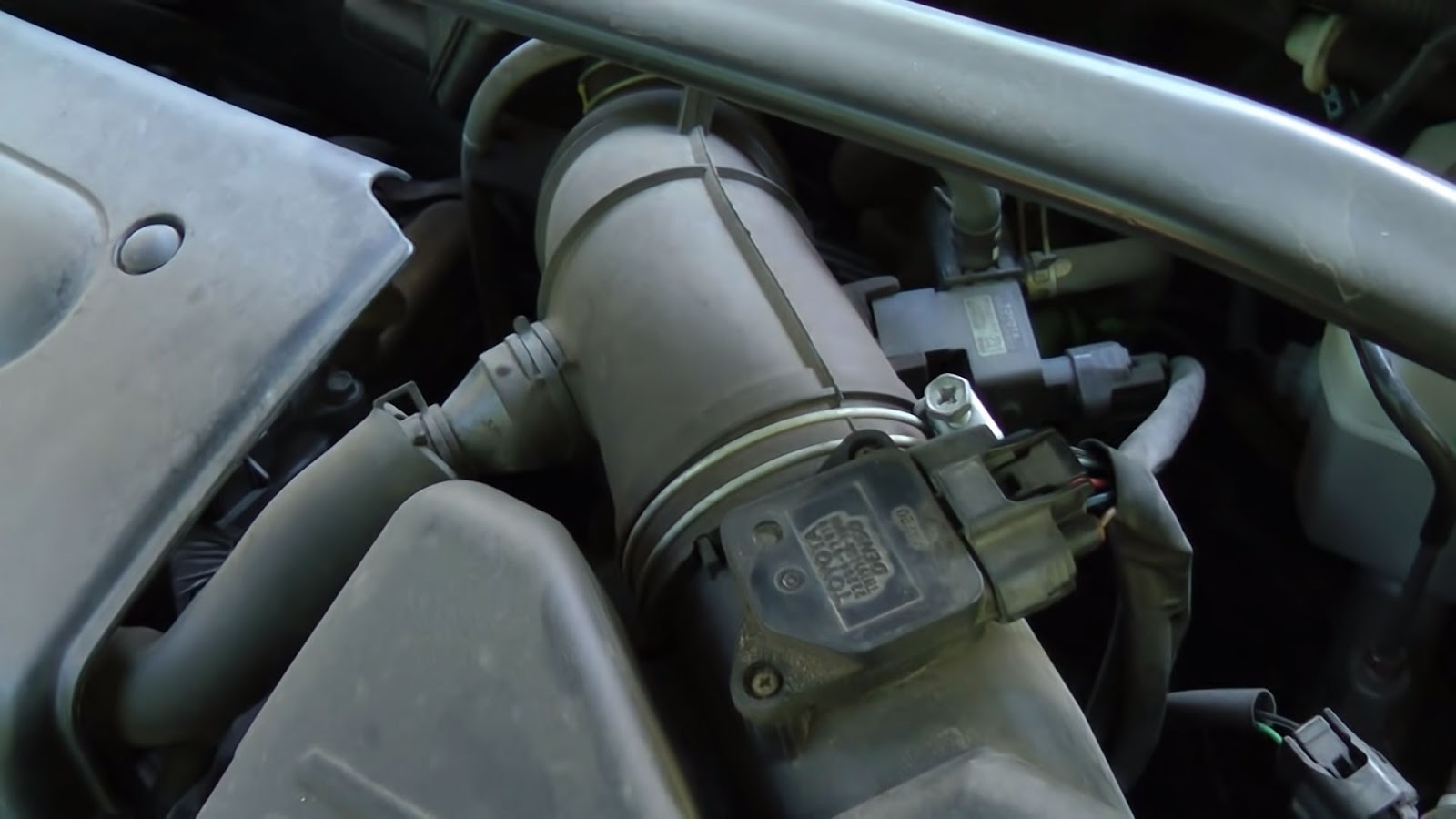
The first step to testing the sensor is to know where it’s located. Since the sensor measures the flow of air, it’s usually located around the intake duct.
Note that it measures the flow of air depending on how open the butterfly valve (throttle body) is. As a result, this sensor is usually before the throttle body. In most cars, the sensor is between the air filter and the throttle body.
How to Test MAF Sensor With a Multimeter
Considering that the sensor uses electric current to do its magic, you can use a multimeter to determine whether it’s working as it should. If you don’t know how to use a multimeter, check out a comprehensive guide on how to use one.
Also, if you don’t have a multimeter, you can buy one that is tailored for cars. With your multimeter ready, follow these steps to test. Note that some cars have 4-wire sensors while others have 5-wire sensors, and the testing procedure can vary slightly.
Test for Ground
Use the following steps to test the sensor ground terminal and verify that the sensor’s ground connection is functioning correctly.
- Put the vehicle in the “OFF” position.
- Turn on your multimeter and set it to the continuity setting (if it has a dedicated one). If not, set it to measure resistance (Ohms, Ω)
- Touch one probe (either one) to a known good ground point on the vehicle. This can be a metal part of the chassis, engine block, or the negative terminal of the battery.
- Touch the other probe to each of the sensor’s terminals one by one. When you find a terminal with very low resistance (close to 0 ohms) or hear a beep (if your multimeter has a continuity beep), this is the ground terminal.
If you get a reading of ‘OL’ or very high resistance, it suggests there’s an open circuit, meaning the ground connection is not good. If the resistance is higher than 0.5 ohms but not ‘OL,’ this could indicate poor ground or a connection with high resistance.
Test the Power Feed Wire
The power feed wire provides the necessary voltage to power the sensor. Turn on your multimeter and set it to 20V DC. Ground the black probe of the multimeter by attaching it to a known good ground point on the vehicle.
Turn the key to the “ON” position such that the vehicle’s electrical system is powered without the engine running. Touch the red probe to each terminal of the sensor’s connector one by one.
Look for a voltage reading that’s consistent with the car manual’s recommended sensor voltages. If you don’t have the manual, the readings should be around 5V (reference voltage) or 12V (direct battery feed). Any of these readings mean the power feed is working correctly.

Test the Signal Wire
The signal wire carries the sensor’s output to the engine control unit (ECU). The MAF signal wire voltage rises as more air flows into the engine. Since you are measuring the sensor output, you need to first reconnect it. This means you might need to back-probe the signal wire with a pin.
Ground the black probe of the multimeter by attaching it to a known good ground point on the vehicle. Connect the red probe to the signal wire pin on the sensor’s connector. This time round, start the car. When the car is idling, the voltage reading should be between 0.5 to 0.7V.
When you rev up the engine to around 2500 to 3500 RPM, the voltage should increase to around 1.5 to 3.0V. The increase and decrease should be steady and consistent with how you are revving up or down the engine. If everything looks steady, even when you wiggle the wires, then the sensor is working correctly.
Test the Frequency Signal Wire
Some sensors use a frequency-based signal rather than a voltage-based signal to communicate airflow data to the ECU. Frequency signals are less susceptible to certain types of electrical noise than analog voltage signals, which is why they are preferred by car manufacturers such as Ford.
To test a frequency-based sensor, you need to set the multimeter to the frequency scale. Just like when testing the voltage signal, connect the black probe to the ground and the red probe to the frequency wire and then start the car.
At idling, the frequency should be around 30 Hz. Again, rev the engine up and down and wiggle the wires to see whether the changes are consistent and steady. If they are steady, then the sensor is working correctly.
Final Thoughts
With the above guide, you now know how the MAF works and how to test a MAF sensor for possible problems. You can also check our guide on the common MAF sensor failure symptoms. If the test shows the sensor is not working correctly, check this guide on how you can fix it.